The production of precision welded parts and assemblies demands a significant investment of time and effort, with much of it centered around quality control and meeting the particular requirements of the application. Design engineers spec and scope every step of production toward meeting those requirements, including exact welding parameters. The more demanding the application, the more demanding the specifications.
In aerospace, biomedical engineering, and other precision industries, application requirements can, and should be, stringent, and no less so for welding requirements. When every part has to function flawlessly, then every weld needs to be laid perfectly and precisely.
Weld certifications are, of course, a gold standard, but not necessarily a one-size-fits-all solution to controlling the quality of welds. As an example, one of the most common weld standards is AMS 2681, which defines the procedures and requirements for joining metals and alloys using the electron-beam welding process. But for some requirements in aerospace, AMS 2681 doesn’t go far enough, and parts must be welded to the even tougher AMS 2680. But for another application, perhaps in a different field, welding to AMS 2681 is overkill and ultimately wasteful.
 |
WebinarWelding 101 Precision Welding Tips for Electron Beam, Laser Welding and Laser Hermetic Sealing |
When does a standard go too far? When is a standard not enough?
Weld certification and standards are, by nature, broad and all-inclusive, and aren’t tailored to specific applications. In many cases, standards were developed long before new technologies or applications were even created. Is a standard welding for cold war era aircraft an appropriate gauge for the performance of your part?
For many modern applications, the solution is to test to the application, and not simply the standard.

Testing to Set the Standard
Testing can offer a clear understanding of the structural viability of a part’s design, and how it will hold up to the rigors of its application. More than a broad, general spec, intelligent testing it can help determine if the design and production will meet the requirements. But how much testing is too much, and how much is too little? How does a designer, and a parts manufacturer, find the “sweet spot,” where the design parameter is met and exceeded, but the testing process doesn’t add excessive or unneeded cost and time to the process?
The key is to have a clear understanding of the test/inspection process in order to choose the right combination to meet the needs of the design, without belaboring the process.
To begin to establish this balance, first one must understand the different testing methods, their advantages and disadvantages, and how to use that knowledge to develop a provable, traceable way to test to your application requirements.
While the methods of weld testing are as varied as the parts themselves, generally they fall into two broad, main categories – Nondestructive and Destructive.
Nondestructive Testing
Nondestructive testing (NDT) involves inspecting, testing, and evaluating materials and assemblies for flaws without destroying the part. One of the most significant advantages of this method is that the part can still be used or sold after the inspection is completed. One of the most common methods used is visual inspection.
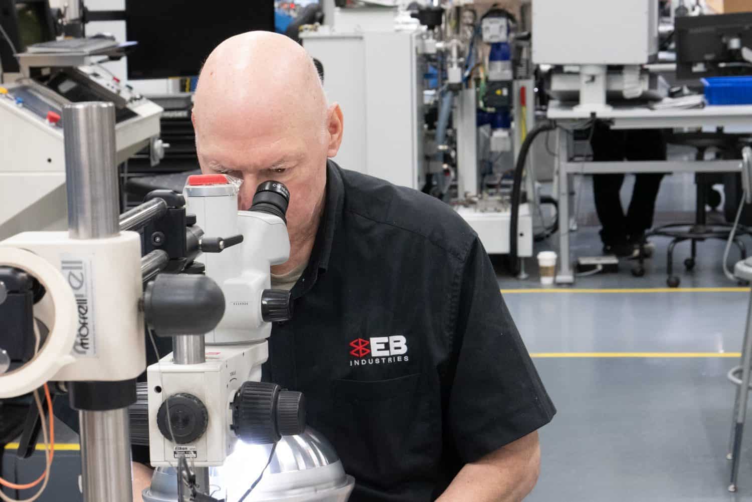
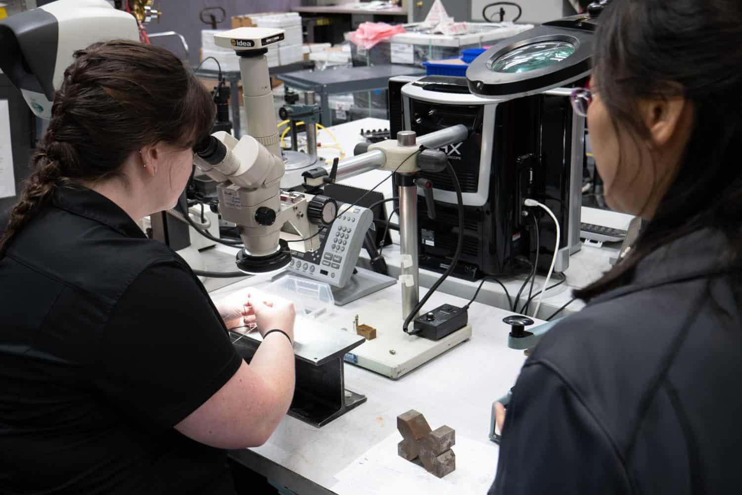
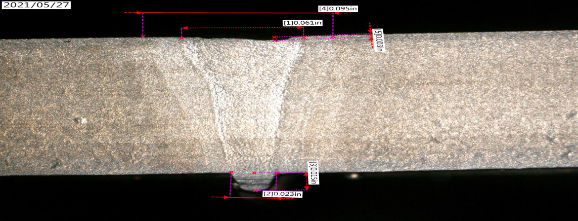
Visual weld inspection is the process in which inspectors look at welds either with the naked eye or, more commonly, under a microscope. At EB Industries, our standard is to inspect parts under 20x magnification to identify surface defects such as cracks, pinholes, underfill and other conditions. This is only performed by technicians who have been certified to our internal procedure, including completing a test using sample hardware visually inspected by a third party NADCAP approved metallurgical lab. The main limitation to this process is that you’re only limited to surface defects and it’s virtually impossible to know what occurred beneath the surface. For a look at the weld below the surface, Radiography or Computed Tomography (CT), is often used in NDT.
Radiography can reveal the presence and nature of internal defects in a weld, such as cracks, holes, slag, and incomplete fusion zones. A CT scan produces a 3D volumetric density map. The 3D volume is generated by the reconstruction of a high number of 2D x-ray images. Many 2D projection images can be combined using intuitive software to produce a 3D volume of practically any part, object, or product.
Although visual inspection is the most used Nondestructive method, there are other ND methods, including:
- Dye Penetrant Inspection
- Mass Spectrometer Helium Leak Testing
Disadvantages of Nondestructive Testing include the need for specialized equipment and the properly trained inspection personnel. Allowances must also be made for the make-up of different metals being scanned, how they are read in the inspection process, and the extra time needed to perform these inspections. There are also certain assembly geometries that can make it difficult to perform some ND inspections.


